How material fatigue causes cracks in safety-critical components
Time
Click Count
Cracks often begin long before anyone can see them
Material fatigue causes cracks when a component experiences repeated stress that is individually below the level needed to break it, but cumulatively sufficient to damage its internal structure. This is why fatigue is especially dangerous in safety-critical equipment: a bracket, shaft, fastener, pressure boundary, landing-gear element, lifting component, or electrical connector can appear sound during routine visual checks and still be approaching failure.
For quality and safety teams, the practical question is not whether cyclic loading exists. Almost every operating asset experiences it through vibration, starts and stops, pressure changes, thermal cycling, rotation, handling, or fluctuating electrical loads. The question is whether the component has enough fatigue resistance, design margin, manufacturing consistency, and inspection coverage for the load spectrum it will actually see.
A fatigue crack is rarely caused by one issue alone. Repeated loading provides the driving force, but local geometry, surface condition, material quality, assembly stress, corrosive exposure, and missed inspection opportunities determine where damage starts and how quickly it becomes critical. Treating fatigue as a simple “material problem” can therefore leave the most controllable risks unaddressed.
The three stages of fatigue damage
Fatigue failure is commonly described in three stages: crack initiation, crack growth, and final fracture. The last stage is often sudden. The first two may occupy most of the component’s useful life and are where quality control has the greatest opportunity to intervene.
1. Crack initiation at a local weak point
Repeated stress is not distributed perfectly evenly through a real component. At holes, threads, keyways, weld toes, sharp internal corners, surface scratches, machining marks, dents, inclusions, and transitions in section thickness, stress can concentrate far above the nominal stress calculated for the overall part. A design may satisfy a general strength calculation while still having a fatigue-sensitive detail at one local feature.
Small surface defects matter because fatigue cracks commonly initiate at or near the surface, where tensile stress is highest and where manufacturing or service damage is most likely to occur. The initial crack may be microscopic. It does not need to be visible to change the local stress field around it.
Material condition also affects initiation. Improper heat treatment, excessive residual tensile stress, poor weld quality, inadequate surface finishing, decarburization, porosity in castings, or non-metallic inclusions can reduce the number of cycles a part can tolerate before a crack forms. These conditions do not guarantee failure, but they make the result more sensitive to load variation and environmental exposure.
2. Progressive crack growth under cyclic loading
Once a crack exists, every load cycle can extend it by a very small amount. Growth is usually faster when the stress range is larger, when peak tensile load is higher, or when the component is exposed to conditions that weaken the crack tip region. The remaining intact cross-section becomes smaller as the crack advances, raising the effective stress in the material that remains.
This progression explains why a component may operate without obvious signs for a long period and then fail within a relatively short interval. The visible condition of the part is not a reliable measure of remaining fatigue life unless the inspection method can detect and size cracks in the relevant locations.
Load sequence also matters. A few unusually severe events can have disproportionate consequences if they create an initial crack or accelerate an existing one. For this reason, a fatigue assessment based only on average operating load can be misleading. Start-up transients, emergency stops, misalignment events, overloads, pressure spikes, road shocks, vibration resonance, and maintenance handling should be considered where they are plausible parts of the service history.
3. Final overload of the remaining section
When the crack reaches a critical size, the remaining material can no longer carry the applied load. The final break may resemble a single overload event, leading investigators to focus only on the last operating condition. Fracture examination often shows a different story: a fatigue region indicating gradual crack propagation and a smaller final-fracture region where the remaining section failed rapidly.
That distinction is important for corrective action. Increasing the component’s static strength may not solve a failure that began because of a sharp notch, poor surface treatment, unanticipated vibration, or an inspection interval that was too long to detect crack growth.
Why “below yield strength” is not a sufficient safety argument
A common misunderstanding is that a component is safe from fatigue if operating stress stays below the material’s yield strength. Yield strength is relevant to permanent deformation under a monotonic load, but fatigue is governed by repeated loading, local stress concentration, mean stress, material response, and the required service life. A part can remain elastic at the macroscopic level while accumulating fatigue damage at a microscopic scale.
Some ferrous materials can exhibit an apparent endurance limit under specific laboratory conditions, but this should not be treated as a universal design exemption. Aluminum alloys, many welded structures, and components exposed to corrosion or variable-amplitude loading may continue to accumulate fatigue damage as cycle count rises. Surface finish, size, geometry, residual stress, temperature, and environment can all make laboratory coupon data a poor substitute for a component-specific assessment.
For safety-critical parts, the usable fatigue performance is therefore a system property. It depends on the material specification, manufacturing route, design detail, joining method, operating loads, installation quality, and inspection plan. A material datasheet alone cannot establish an acceptable fatigue life for an assembled component in service.
Conditions that make fatigue cracks more likely
Quality personnel should look beyond the base material grade when assessing whether a crack risk deserves escalation. Several conditions repeatedly create a gap between expected and actual fatigue performance:
- Stress raisers: sharp radii, thread roots, holes, weld toes, abrupt thickness changes, tool marks, and contact damage increase local stress.
- Variable or poorly characterized loading: vibration, cyclic pressure, rotating loads, thermal expansion, and intermittent impacts may create a wider stress range than nominal duty data suggests.
- Residual tensile stress: welding, forming, grinding, machining, and poor assembly alignment can leave a component more vulnerable before service loading begins.
- Surface degradation: corrosion pits, fretting, abrasion, coating damage, and accidental scratches can become crack initiation sites.
- Manufacturing discontinuities: porosity, lack of fusion, inclusions, laps, seams, or heat-treatment variation can reduce the margin assumed in design.
- Incorrect assembly conditions: excessive or insufficient fastener preload, misalignment, loose fits, and unintended contact can alter the load path and introduce cyclic bending.
Corrosion-fatigue and fretting-fatigue deserve particular attention because they can defeat assumptions based on dry, controlled test conditions. Corrosion pits create highly localized stress concentrations. Fretting occurs where two contacting surfaces experience small relative motions under load, producing wear debris and surface damage that can initiate cracks. A component may meet its material and dimensional requirements at release, then become fatigue-sensitive because the operating environment or assembly interface changed.
Inspection must be tied to the expected damage mechanism
Visual inspection remains useful for identifying deformation, corrosion, coating failure, loose hardware, or gross cracking. It is not enough when the concern is early fatigue damage in a concealed, highly stressed, or inaccessible region. Inspection planning should begin with a clear answer to three questions: where is a crack most likely to initiate, what crack size must be found before it becomes critical, and which method can reliably detect that crack in that location?
Different non-destructive testing methods answer different questions. Dye penetrant testing can reveal surface-breaking defects on suitable non-porous materials. Magnetic particle testing is effective for locating surface and near-surface discontinuities in ferromagnetic materials. Eddy-current testing can be valuable around holes, fasteners, and conductive surfaces, while ultrasonic methods can identify certain internal flaws and crack geometries. Radiographic techniques may be useful for volumetric discontinuities or specific weld conditions, but they are not a universal answer for tight planar fatigue cracks.
The method is only part of the control. Probe access, surface preparation, coating condition, orientation of the expected crack, calibration, acceptance criteria, operator qualification, and reporting discipline determine whether a result is meaningful. An inspection that cannot reliably interrogate the likely initiation zone should not be treated as proof that fatigue damage is absent.
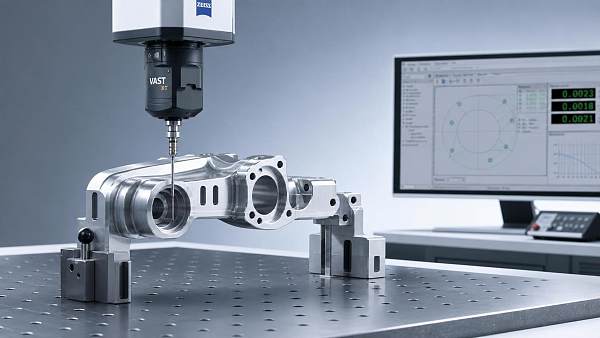
For production components, measurement data should also be used upstream of final inspection. Dimensional verification can identify radius deviations, hole position errors, out-of-roundness, or misalignment that changes loading. Surface roughness and profile measurement can confirm whether a fatigue-sensitive finish requirement has been achieved. Process monitoring can expose drift in machining, welding, heat treatment, shot peening, tightening, or coating operations before it becomes a field reliability issue.
How standards should be used in a fatigue-control program
Standards provide test methods, terminology, qualification approaches, and traceability expectations, but they do not remove the need for engineering judgment. A fatigue test performed under one stress ratio, frequency, specimen geometry, environment, and load mode may not represent a component subjected to a different duty cycle. The purpose of standards is to make methods repeatable and results interpretable, not to justify transferring data outside its valid conditions.
Common references include ASTM and ISO fatigue-test methods for metallic materials, fracture-mechanics methods for fatigue crack-growth assessment, and sector-specific rules for welded structures, pressure equipment, transport assets, and aerospace hardware. Non-destructive testing programs may also need to align with applicable personnel-qualification and procedure requirements. The applicable document set depends on the regulated sector, component function, material, and jurisdiction.
A defensible fatigue-control file should connect the following items rather than keeping them as separate records:
- the intended load spectrum and foreseeable abnormal loads;
- material, heat-treatment, joining, and surface-condition requirements;
- critical geometry and tolerances;
- the rationale for design life or inspection interval;
- the chosen NDT method, coverage, detection capability, and acceptance criteria;
- traceable records for manufacturing, inspection, repairs, deviations, and service events.
This linkage matters when a failure, repair, design change, or supplier change occurs. Without it, teams may know that a crack was found but be unable to determine whether the cause was material variability, a process escape, an altered load path, insufficient inspection sensitivity, or an invalid life assumption.
What to do when a fatigue crack is found
A discovered crack should trigger more than a disposition decision for the affected item. First, establish whether the crack is in a safety-critical location and whether similar components share the same design, lot, process route, installation condition, or service exposure. Then preserve evidence before grinding, blending, welding, or replacing the part. The fracture surface, location, orientation, and surrounding condition can provide essential clues about initiation.
Containment may require targeted inspection of the population, but scope should be based on exposure rather than convenience. Components with similar cycle counts, environments, loading histories, or manufacturing records may deserve priority even when they are not physically close to the first finding. Repeated replacement without correcting the initiating mechanism merely restarts the fatigue clock.
The corrective action should correspond to the mechanism. A geometry-driven crack may require a radius change, surface-finish improvement, or stress-relief treatment. A vibration-driven crack may require a support, stiffness, balance, alignment, or operating-control change. A corrosion-assisted crack may require environmental sealing, drainage, coating revision, or inspection adjustment. Where crack growth cannot be eliminated, damage-tolerant management may be appropriate only when crack detectability and inspection intervals are demonstrably sufficient for the consequence of failure.
Material fatigue becomes hazardous when it is treated as an unpredictable event. In most cases, it follows a traceable chain: cyclic load acts on a local weakness, a crack initiates, the crack grows, and the remaining section eventually fails. Quality and safety management are most effective when that chain is made visible through realistic load assumptions, controlled manufacturing details, targeted measurement, and inspection methods capable of finding damage before the final fracture does.
Recommended News
 Sep 16, 2026How to choose monitor stands that reduce neck strain at workMonitor stands can reduce neck strain by improving screen height, distance, and stability. Explore practical tips to choose the right ergonomic stand for a more comfortable workspace.
 Sep 15, 2026How to verify an importers directory for machinery before contacting suppliersImporters directory for machinery verification guide: assess legal status, technical fit, compliance, and service capability to build a reliable supplier shortlist.
 Sep 13, 2026How to assess calibration support from metrology suppliers in the Middle EastMetrology suppliers Middle East: learn how to assess ISO/IEC 17025 scope, calibration uncertainty, local support, turnaround time, and lifecycle cost.
 Sep 12, 2026How material fatigue causes cracks in safety-critical componentsMaterial fatigue can trigger hidden cracks in safety-critical components long before visible failure. Learn how cyclic loading, stress concentrations, inspection methods, and targeted controls reduce risk.
 Sep 10, 2026What to verify before choosing an optical micrometer supplier for wireChoose an optical micrometer supplier for wire with confidence. Verify real-line accuracy, calibration, integration, and support before you buy.
 Sep 08, 2026How to choose thickness gauges for pipes with limited accessThickness Gauges for pipes: learn how to select the right ultrasonic gauge and probe for tight access, curved surfaces, corrosion, coatings, and reliable readings.
 Sep 07, 2026How to choose anti-aging face serums for your skin typeantiagingfaceserums made simple: discover the best ingredients, textures, and routines for dry, oily, sensitive, or combination skin—plus tips for visible results.
 Sep 05, 2026How to choose sheet metal components for tight-tolerance assembliesSheet metal components for tight-tolerance assemblies: learn how to align materials, datums, forming, finishes, and inspection for reliable fit and repeatable performance.
 Sep 04, 2026What accuracy should a digital temperature humidity sensor have?Digital temperature humidity sensor accuracy explained: compare temperature and RH limits, resolution, drift, calibration, and installation effects to choose reliable performance for your application.
 Sep 03, 2026How to choose glamping tents for eco resorts in high-wind locationsGlamping Tents for eco resorts: discover how to choose wind-resistant structures, engineered anchors, and durable materials for safer, sustainable stays.
 Sep 02, 2026How to assess a bore gauge manufacturer in Latin America for measurement reliabilityBore gauge manufacturer Latin America: learn how to verify calibration traceability, repeatability, service support, and shop-floor reliability before you buy.
 Sep 01, 2026What accuracy factors matter most in advanced metrology calibration?Advanced metrology calibration: discover the key accuracy factors—from traceability and uncertainty to environment, probes, and software—for reliable decisions.
 Aug 31, 2026When does legal tech make sense for a growing business?Legal tech helps growing businesses streamline contracts, compliance, IP, and audit controls. Discover the key signals, practical tools, and steps to scale with confidence.
 Aug 30, 2026How manufacturing tolerance affects thread gauge acceptance limitsThread gauge manufacturing tolerance affects acceptance limits, calibration confidence, wear risk, and inspection consistency. Learn how to prevent costly thread gauge errors.
 Aug 29, 2026How to choose office supplies that reduce waste in shared workspacesOffice supplies can cut waste and costs in shared workspaces. Discover practical procurement tips for durable, refillable, low-packaging products.
 Aug 28, 2026How to compare metrology equipment vendors for calibration supportMetrology equipment vendors: compare calibration scope, ISO/IEC 17025 support, downtime, documentation, and lifecycle costs to choose reliable service.
 Aug 27, 2026What to evaluate before choosing industrial inspection systems in AsiaIndustrial Inspection Systems Asia: evaluate accuracy, cycle time, automation, traceability, and local service to choose a reliable solution for smarter quality control.
 Aug 26, 2026Do dermarollers actually improve absorption of skincare productsDermarollers can improve skincare absorption, but not always safely. Learn when they help, which products to pair, and how to avoid irritation for better skin results.
 Aug 25, 2026What makes a high accuracy CMM probe reliable at tight tolerancesHigh accuracy CMM probe reliability depends on repeatability, stylus stability, calibration integrity, and system fit. Learn what ensures trusted results at tight tolerances.
 Aug 24, 2026When does an automated trade platform make sense for growing teams?Automated trade platform adoption makes sense when growing teams face supplier complexity, compliance risk, and limited visibility. Learn the signs, ROI factors, and how to scale with control.
 Aug 22, 2026How to vet an industrial measurement equipment supplier for calibration traceabilityIndustrial measurement equipment supplier selection starts with calibration traceability. Learn how to verify ISO/IEC 17025 evidence, uncertainty, and audit-ready documentation.
 Aug 20, 2026What is driving demand in the optical metrology market right nowOptical metrology market demand is rising as manufacturers need faster, non-contact, high-precision inspection for semiconductors, EVs, electronics, and automated production lines.
 Aug 18, 2026How to integrate a digital gauge RS232 output with SPC softwareDigital gauge RS232 output integration with SPC software: learn how to ensure stable data capture, traceability, and scalable deployment while avoiding hidden quality risks.
 Aug 17, 2026What export insights reveal about freight cost planningExport insights reveal how shipping patterns, documentation, and supplier readiness shape real freight costs. Learn smarter planning tactics to cut hidden fees and reduce risk.