How to interpret accuracy on measurement device specification sheets
An accuracy claim of ±0.1% becomes useful only when you know its reference, operating conditions, and additional error terms. Headline percentages alone cannot establish suitability.
For technical evaluators, the practical question is whether the instrument’s applicable error limits and measurement uncertainty support reliable decisions across the actual operating range.
This guide explains how to decode measurement device specification sheets, compare competing instruments, and identify conditions that could undermine an otherwise attractive accuracy claim.
Start with the complete error expression, not the headline percentage
Before comparing devices, identify the measured quantity, selected range, expected readings, environmental conditions, and calibration interval. These determine which specification actually applies to your application.
Then locate the complete accuracy statement, including footnotes. A prominent percentage may exclude offset, temperature effects, probe contributions, or restrictions documented elsewhere in the datasheet.
Your first calculation should convert the applicable specification into an absolute error limit at representative operating points, expressed in volts, millimeters, degrees, or another relevant unit.
This makes comparisons meaningful. Two instruments advertising identical percentages can produce substantially different error limits when their ranges, resolutions, or reference conditions differ in practice.
Treat any missing definition as an evaluation gap. Ask the supplier to clarify the applicable limit before using that number in an acceptance decision.
Does the percentage apply to the reading or full scale?
A percentage of reading scales with the measured value. A percentage of full scale generally remains constant for a selected range, regardless of the reading.
Suppose two pressure instruments both advertise ±0.1%. One specifies reading, while the other specifies full scale on a range extending from zero to 100 bar.
At a reading of 10 bar, their stated error limits differ tenfold. At lower pressures, the difference becomes even more significant for process acceptance decisions.
Confirm how the manufacturer defines full scale, range, and span. These terms can differ, particularly for bipolar instruments or transmitters with configurable measurement ranges.
Do not assume that a selectable display range changes the underlying accuracy basis. Some devices retain an error contribution tied to their original sensor range.
How do you calculate percentage plus counts or digits?
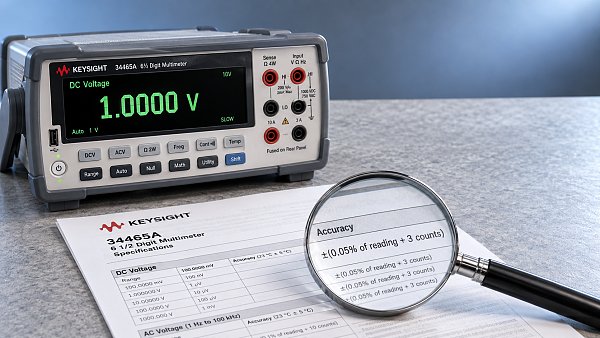
Digital multimeters frequently specify accuracy as ±(percentage of reading + counts). The count term converts display resolution into an additional absolute error allowance for evaluation.
Consider a meter on its 10 V range, displaying 1.0000 V with 0.0001 V resolution and accuracy specified as ±(0.05% of reading + 3 counts).
The reading contribution is 0.0005 V. Three counts contribute 0.0003 V. Adding these terms gives a specified error limit of ±0.0008 V, or ±0.8 mV.
At 0.1000 V on the same range, the percentage contribution falls to 0.00005 V, while the count contribution remains 0.0003 V under the stated specification.
The resulting ±0.00035 V limit equals ±0.35% of that reading. This explains why performance near the bottom of a range can disappoint despite an attractive percentage.
Check what digits or counts mean in that specific document. Autoranging, measurement speed, filtering, and display modes can change the applicable resolution or accuracy specification.
Which specifications describe accuracy, and which describe something else?
Accuracy describes closeness to a reference value. In formal metrology, it is qualitative; datasheet accuracy numbers usually represent specified error limits under defined conditions.
Resolution is the smallest indicated increment or detectable change under stated conditions. A finely divided display does not establish that its displayed values are correct.
Repeatability describes agreement among repeated measurements under specified repeatability conditions. Consistent results can still contain substantial systematic error, such as an uncorrected sensor offset.
Linearity describes departure from a specified reference relationship across a range. It may exclude zero offset, sensitivity error, hysteresis, or other contributions unless explicitly stated.
Measurement uncertainty characterizes the dispersion of values attributed to the measurand. It accounts for relevant information about the complete measurement process, including corrections and residual effects.
Keep these quantities separate during procurement. A scanner’s point spacing, a camera’s pixel count, and a sensor’s repeatability cannot independently establish dimensional measurement accuracy.
Which operating conditions can invalidate the stated limit?
Most accuracy specifications depend on reference conditions. Check ambient temperature, humidity, warmup, power supply, installation orientation, and the time elapsed since calibration or adjustment.
A device may operate from −10°C to 50°C while meeting its headline accuracy only between 18°C and 28°C. Operating limits and accuracy conditions serve different purposes.
Suppose a datasheet requires adding 0.01% of reading per degree Celsius outside that reference band. At 38°C, the additional contribution is 0.10% of reading.
Apply that term according to the manufacturer’s formula. Some temperature coefficients include separate range contributions, and some specified limits already incorporate temperature effects across a stated interval.
Check whether the instrument offers different accuracy tables for 24 hours, 90 days, or one year after calibration. Use the interval matching your maintenance plan.
For dynamic measurements, also inspect bandwidth, response time, settling, and sampling conditions. Excellent static accuracy does not establish accurate capture of fast transients or vibration.
How should you combine error terms without double counting?
When a specification explicitly uses an additive expression, calculate each term in consistent units and add their magnitudes to obtain the stated error limit.
Do not replace that addition with root-sum-square simply because the result looks more favorable. The manufacturer’s specification defines how its published limit should be calculated.
Building an uncertainty budget is a separate exercise. Contributions require appropriate probability models, sensitivity coefficients, and consideration of correlation before they can be combined meaningfully.
For example, a rectangular distribution may justify dividing a bounded contribution by √3, but that assumption requires support; it does not follow automatically from ± notation.
Look for overlap before adding contributions. A total accuracy specification may already include linearity, hysteresis, and repeatability, making their separate addition an unnecessary duplication.
Likewise, calibration uncertainty and a manufacturer’s accuracy allowance may overlap. Decide whether you are evaluating specified performance or corrected measurement results with an uncertainty budget.
Does calibration prove that the instrument meets your requirements?
A calibration certificate reports measurement results and associated uncertainty under stated conditions. It does not automatically establish conformity across every range, function, or operating environment.
Review the actual calibration points against your application. A device checked near full scale may provide limited evidence about performance close to your critical lower limit.
Distinguish calibration from adjustment. Calibration establishes measurement relationships; adjustment changes the instrument’s response. An instrument can be calibrated and still fail an applicable acceptance requirement.
When a certificate states conformity, identify the specification, decision rule, and treatment of uncertainty. These determine how borderline results were classified as passing or failing.
ISO/IEC 17025 accreditation supports laboratory competence within an accredited scope. Verify that the scope covers the relevant quantity, range, method, and uncertainty capability for your application.
Metrological traceability requires a documented, unbroken calibration chain, with each calibration contributing uncertainty. A general claim of NIST traceability does not replace this evidence.
How do you decide whether a device is good enough?
Begin with the permissible error in the product or process, then allocate a defensible portion to measurement. Include consequences of incorrect acceptance or rejection.
Suppose a component dimension has limits of 25.000 ±0.020 mm. An instrument error limit of ±0.015 mm already consumes much of the available half-width.
Even if that instrument appears adequate from its datasheet, fixturing, alignment, temperature, operator technique, and workpiece behavior may leave the complete measurement process unsuitable.
Assess the uncertainty of the actual measurement process before defining acceptance limits. Where appropriate, guard bands can reduce false acceptance risk while increasing possible false rejections.
A 4:1 ratio can serve as an initial screening convention, but define its numerator and denominator. Tolerance, error limits, and expanded uncertainty are not interchangeable.
The final decision should reflect the agreed decision rule and risk requirements. No universal ratio guarantees suitability across every manufacturing, laboratory, or regulatory application.
What changes when you compare different measurement technologies?
Apply the same interpretation method across technologies, but expect different dominant error sources. The useful specification must correspond to the quantity and measurement task.
For a length-dependent specification such as E = A + L/K, confirm the units of every term and evaluate it at the actual measured length.
For optical or vision equipment, ask whether published results describe ideal targets or representative production surfaces. Reflectivity, texture, and geometry can materially change measurement performance.
For gas analyzers, distinguish detection limit from quantitative accuracy. Detecting a low concentration does not establish that the reported concentration meets your required error limit.
Build a comparison that supports a defensible decision
Compare candidates using identical measurement points, required throughput, environmental assumptions, and calibration intervals. Record both calculated error limits and any unresolved exclusions in the specification.
Ask suppliers to confirm the complete applicable specification in writing, including accessories and operating modes. Request application testing when published evidence leaves a consequential gap.
The best reading of measurement device specification sheets connects every accuracy claim to an actual operating condition, calculated limit, and requirement for measurement performance.
Select the instrument whose documented performance supports your acceptance decisions throughout its intended use. A smaller headline percentage matters only when the complete measurement evidence supports it.