Can a Profile Projector Replace Manual Visual Inspection?
Time
Click Count
Can a Profile Projector Replace Manual Visual Inspection?
Can a profile projector replace manual visual inspection? For quality teams evaluating machined parts, stamped components, or precision tooling, the answer depends on what needs to be inspected. A profile projector can turn subjective judgments about edges, angles, and dimensions into measurable comparisons, but it cannot replace every check for surface defects, color variation, or hidden features.
The distinction is practical: replacing someone’s judgment that an edge “looks about right” is not the same as replacing the person inspecting the part. Most conventional profile projectors still depend on an operator to position the component, establish alignment, select features, and interpret the image. They make certain judgments more defensible; they do not automatically make inspection autonomous.
For many workshops, the best outcome is therefore partial replacement: optical measurement for accessible geometry, with visual examination retained for appearance and damage. Whether that split works depends on the drawing, the defect risks, and the production workload—not simply the magnification printed on the lens.
Where the projector changes the quality decision
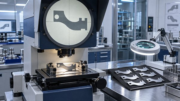
A profile projector, also called an optical comparator, projects an enlarged image of a component onto a screen. Transmitted illumination produces a silhouette; reflected illumination, where fitted, helps reveal visible surface features. Depending on the instrument, operators can compare the image with an overlay or measure coordinates, distances, and angles using the stage and readout.
That matters when the acceptance requirement is geometric. Consider a stamped bracket with an external radius and an edge notch. Looking at it under a bench magnifier may reveal an obvious deformation, but it does not establish whether the radius or notch position meets the drawing. A correctly configured optical comparator can provide a dimensional result or a controlled contour comparison.
The same reasoning applies to accessible profiles on turned parts, cutting tools, and small molded components. If the feature can be presented clearly in the measurement plane, projection may offer a useful alternative to trying to judge it by eye or reaching it with a contact tool.
However, the projector only sees the presented view. An apparently correct outline does not prove that a part has the correct thickness, that a hole is cylindrical, or that an out-of-plane feature is positioned correctly. A two-dimensional image cannot establish every three-dimensional requirement.
A sharp silhouette is not a complete defect inspection
Surface condition is where replacement claims often become too broad. Scratches, discoloration, contamination, coating variation, and shallow dents may need directional lighting, several viewing angles, or a dedicated microscope. Some are visible under reflected illumination on a projector, but visibility alone does not establish a reliable detection method.
A burr illustrates the problem. A burr extending beyond the projected edge may be obvious. One lying on the upper surface, inside a recess, or along an edge hidden by the fixture may not appear in the silhouette. Rotating the part can expose additional defects, but it also adds handling time and creates opportunities to miss a required view.
Manual visual inspection has its own weaknesses: lighting varies, attention drifts, and different inspectors may classify the same mark differently. Yet a trained inspector can deliberately change the viewing angle and investigate an unexpected feature. That flexibility remains valuable for irregular damage and cosmetic acceptance, provided the inspection instructions define what is acceptable.
Neither method establishes freedom from hidden cracks or internal defects. Those requirements may call for an appropriate nondestructive testing method rather than a better magnifier or a larger projection screen.
The fixture can matter as much as the optics
A common source of disagreement is not the screen image but the way the part sits on the stage. Tilt can alter the projected shape. A cylindrical part that rolls slightly between measurements can present a different edge. A thin stamped component may distort if the fixture presses it flat when the drawing requires measurement in its free state.
Start with the datum scheme and measurement condition. The fixture should locate the part consistently without obscuring the feature or changing its shape. For soft or flexible components, non-contact optical measurement does not eliminate deformation caused by the support itself.
Focus also needs a defined practice. On a thick component, different edges may lie at different depths. An operator can obtain a crisp image of one edge while another remains less distinct. Treating every visible boundary as equally measurable invites inconsistent results.
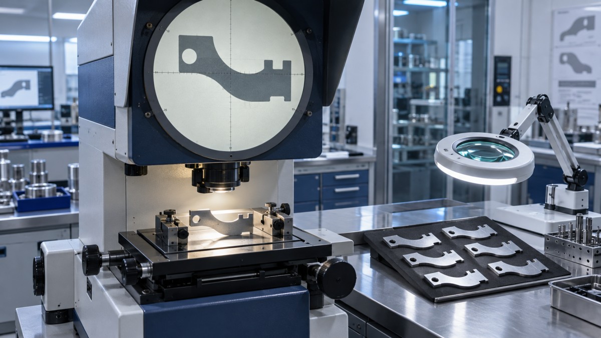
For recurring work, document the part orientation, locating surfaces, illumination mode, lens, and measurement sequence. A reference image of the correct setup can prevent more disagreement than a general instruction to “check on projector.”
Magnification is not measurement capability
A larger image makes small features easier to see. It does not, by itself, prove that the instrument can support a particular tolerance. Capability depends on the stage, optical performance, calibration, environment, fixture, and operator’s ability to identify the same edge repeatedly.
A fine digital readout is equally easy to overinterpret. Display resolution describes the increments shown on the screen, not the uncertainty of the complete measurement. If repeated loading and alignment produce appreciable variation, extra displayed digits will not resolve the problem.
Calibration should cover the functions actually used. Stage displacement, angular measurement, and projected magnification may require different checks. For screen overlays, confirm that the overlay matches the selected magnification and is properly registered. A dimensional result obtained through stage movement is not the same measurement process as a visual comparison against an enlarged template.
Traceability also needs careful wording. ISO/IEC 17025 addresses laboratory competence; it is not a blanket certification of a projector’s suitability for every part. A calibration certificate is evidence to examine, including its scope and uncertainty, rather than a substitute for evaluating the inspection task.
For results near a specification limit, define the conformity decision rule before production inspection begins. Depending on contractual requirements and the uncertainty involved, a result just inside the limit may need further review. There is no universal tolerance-to-uncertainty ratio that automatically makes every application acceptable.
Throughput depends on handling, not just measurement speed
For low-volume, varied production, a manual optical comparator can be a sensible compromise. It accommodates different part shapes without demanding an automated inspection program for each one. That flexibility is useful for toolroom checks, first-piece approval, and investigating a dimensional concern.
At higher volumes, loading, alignment, stage movement, and recording results can become the bottleneck. Measure the entire cycle: cleaning the part, placing it, establishing datums, checking all required features, documenting the result, and unloading. Timing only the moment when the operator reads a dimension gives a misleading picture.
An automated vision system may be better suited to repeated, well-defined checks on consistently presented parts. It brings different demands, however: controlled lighting, validated feature detection, stable fixtures, and procedures for rejected or ambiguous results. A digital readout or camera attached to a projector should not be assumed to provide that level of automation.
Also separate inspection capability from sampling strategy. A projector can improve a dimensional check while leaving the risk of uninspected parts unchanged. Whether to inspect every component or a sample requires its own quality and process-risk assessment.
Prove the replacement on representative parts
A useful trial is less about demonstrating a clean image and more about finding where the proposed method breaks down. Include typical parts, challenging finishes, difficult orientations, and examples near acceptance limits where available. Clearly acceptable samples alone will not reveal how inspectors handle borderline conditions.
- Assign each requirement to a method: contour measurement, surface examination, or another dimensional or defect test.
- Repeat measurements after removing and reloading the part, rather than leaving it fixed on the stage.
- Compare operators to expose differences in alignment, focusing, and edge selection.
- Check disputed dimensional results against a suitable reference method with understood uncertainty.
- Record complete inspection time and the reasons parts require additional examination.
For dimensional measurements, a repeatability and reproducibility study can help characterize operator and equipment variation. For subjective defect classification, an attribute agreement study is more appropriate. These answer different questions; consistent dimension readings do not prove consistent scratch detection.
This task-based comparison fits the measurement-to-action approach behind Global Intelligent-Measurement & Sensory-Tech (G-IMS). Its coverage of metrology, industrial optics, and non-contact vision provides a useful framework for separating measurement capability from defect detection and production integration. The relevant question is not which technology looks most advanced, but which produces trustworthy evidence for the required decision.
Replace the judgment that can be measured
A profile projector can replace unaided visual judgments about accessible contours and dimensions when the setup, uncertainty, and acceptance rules support the drawing requirements. It should not automatically replace checks for surface damage, appearance, hidden geometry, or defects outside the selected view.
Before removing a manual inspection step, identify exactly what that step was catching. Demonstrate that the proposed optical method catches it reliably, or retain a complementary check. The result may be a narrower replacement than originally planned—but a much stronger inspection process.
Recommended News
 Oct 19, 2026How to interpret accuracy on measurement device specification sheetsDecode measurement device specification sheets to compare accuracy, calculate error limits, and spot hidden conditions. Make confident instrument choices with this practical guide.
 Oct 16, 2026How to connect smart industrial sensor systems to existing PLCsConnect smart Industrial Sensor Systems to existing PLCs using I/O, IO-Link, or gateways. Explore practical steps to reduce downtime, verify compatibility, and ensure reliable control.
 Oct 15, 2026Can a portable hardness tester for steel measure thin parts accurately?Can a portable hardness tester for steel measure thin parts accurately? Compare UCI and Leeb methods, understand thickness limits, and learn how to validate results before choosing a tester.
 Oct 19, 2026Can a Profile Projector Replace Manual Visual Inspection?Can a profile projector replace manual visual inspection? Discover where optical measurement improves accuracy, which checks still need human judgment, and how to validate your inspection process.
 Oct 18, 2026When Should Thread Plug Gauges Be Replaced?When should thread plug gauges be replaced? Learn how wear limits, damage and calibration results guide replacement decisions to prevent inspection errors and protect product quality.
 Oct 17, 2026How Do Thread Plug Gauges Prevent Threaded-Hole Inspection Errors?How do thread plug gauges prevent threaded-hole inspection errors? Discover GO/NO-GO checks, gauge selection, and handling tips to reduce false results and improve quality.
 Oct 12, 2026How to select thread plug gauges for machining tight-tolerance partsThread Plug Gauges for machining tight-tolerance parts: learn how to select GO/NO-GO gauges by thread class, material, calibration, coatings, and blind-hole requirements.
 Oct 09, 2026How to perform caliper uncertainty analysis for critical dimensionsCaliper uncertainty analysis for critical dimensions: learn to build reliable budgets, manage tolerance risk, and make confident inspection decisions.
 Oct 07, 2026When do supply chain management solutions justify their cost?Supply chain management solutions justify their cost by reducing shortages, excess inventory, and risk. Learn the approval test for measurable ROI.
 Oct 06, 2026What to verify before choosing an industrial equipment supplier in GermanyIndustrial & Manufacturing equipment supplier in Germany: verify compliance, calibration, service, integration, and lifecycle support before choosing the right partner.
 Sep 28, 2026How to verify a NIST standards reference in a calibration reportNIST standards reference verification made simple: learn how to review calibration traceability, uncertainty, ISO/IEC 17025 scope, and report red flags.
 Sep 27, 2026When a dial bore gauge is accurate enough for production inspectionDial bore gauge accuracy for production inspection: learn how tolerance, setup, alignment, surface condition, and guard bands determine reliable bore measurement decisions.
 Sep 26, 2026What size cat tree and tower is right for an indoor cat?Cattreesandtowers guide: find the ideal cat tree size for your indoor cat, with tips on height, platform space, stability, scratching posts, and safe multi-cat setups.
 Sep 24, 2026What drives sensory technology cost in industrial monitoring projects?Sensory technology cost in industrial monitoring depends on accuracy, integration, calibration, software, and lifecycle support. Learn how to build a reliable budget and avoid hidden project costs.
 Sep 18, 2026How to evaluate quality control at a CNC machining factoryEvaluate a CNC machining factory with practical checks for inspection, calibration, traceability, sampling, and corrective actions to secure reliable parts.
 Sep 17, 2026How to select inline measurement systems for Middle East heatInline Measurement Systems Middle East: learn how to select reliable solutions for heat, dust, vibration, calibration, and production-ready data integration.
 Sep 16, 2026How to choose monitor stands that reduce neck strain at workMonitor stands can reduce neck strain by improving screen height, distance, and stability. Explore practical tips to choose the right ergonomic stand for a more comfortable workspace.
 Sep 15, 2026How to verify an importers directory for machinery before contacting suppliersImporters directory for machinery verification guide: assess legal status, technical fit, compliance, and service capability to build a reliable supplier shortlist.
 Sep 13, 2026How to assess calibration support from metrology suppliers in the Middle EastMetrology suppliers Middle East: learn how to assess ISO/IEC 17025 scope, calibration uncertainty, local support, turnaround time, and lifecycle cost.
 Sep 12, 2026How material fatigue causes cracks in safety-critical componentsMaterial fatigue can trigger hidden cracks in safety-critical components long before visible failure. Learn how cyclic loading, stress concentrations, inspection methods, and targeted controls reduce risk.
 Sep 10, 2026What to verify before choosing an optical micrometer supplier for wireChoose an optical micrometer supplier for wire with confidence. Verify real-line accuracy, calibration, integration, and support before you buy.
 Sep 08, 2026How to choose thickness gauges for pipes with limited accessThickness Gauges for pipes: learn how to select the right ultrasonic gauge and probe for tight access, curved surfaces, corrosion, coatings, and reliable readings.
 Sep 07, 2026How to choose anti-aging face serums for your skin typeantiagingfaceserums made simple: discover the best ingredients, textures, and routines for dry, oily, sensitive, or combination skin—plus tips for visible results.
 Sep 05, 2026How to choose sheet metal components for tight-tolerance assembliesSheet metal components for tight-tolerance assemblies: learn how to align materials, datums, forming, finishes, and inspection for reliable fit and repeatable performance.