How temperature affects sub-micron optical measurement accuracy
Time
Click Count
Temperature changes can influence optical measurement accuracy long before they become noticeable to operators. Thermal expansion, refractive-index variations and sensor drift can all introduce errors that matter at sub-micron tolerances. For technical evaluators, understanding these effects is essential when comparing Sub-Micron Precision Measurement optical systems and assessing their suitability for demanding production environments. The central question is not simply whether a machine can resolve a small displacement, but whether it can measure the intended feature with defensible uncertainty under the temperatures it will actually encounter.
A stable room does not guarantee a stable measurement
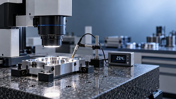
Temperature affects several parts of the measurement chain at once: the workpiece, fixture, machine structure, optical path and sensor electronics. These elements rarely respond at the same rate. A room may return to its setpoint after a door opens, while a large component or granite base remains out of equilibrium for considerably longer. Conversely, internal heat from a camera, motor or illumination source can create a local gradient even when the room sensor reports a steady temperature.
This distinction matters when comparing specifications. An operating temperature range describes conditions in which equipment can function; it does not necessarily describe the conditions under which a stated accuracy or maximum permissible error applies. Evaluators should look for the associated temperature range, permitted rate of change, warm-up period, measurement volume and any required compensation. A specification without those conditions is difficult to translate into production performance.
Resolution is also not accuracy. A system may display nanometre-scale increments while its measured position shifts by a much larger amount as the structure warms. High resolution can make drift visible; it cannot, by itself, remove it.
Workpiece expansion can consume the error budget
A dimensional measurement normally refers to a specified reference temperature. ISO 1 defines 20 °C as the standard reference temperature for geometrical product specification and verification. That does not mean every measurement must physically occur at 20 °C. It means that, when dimensions are specified at that reference, the result must be interpreted or corrected accordingly.
For a uniform material over a modest temperature difference, the approximate length change is ΔL = αLΔT, where α is the coefficient of linear thermal expansion, L is length and ΔT is the change in temperature. As an illustration, a 100 mm length made from a material with an assumed coefficient of 12 × 10−6/°C changes by approximately 1.2 µm for a 1 °C temperature change. The coefficient is an example, not a substitute for the material data applicable to a specific component.
The calculation becomes less straightforward when the part is not uniform. A coated component, bonded assembly or additively manufactured part may have directional or locally varying expansion. A temperature probe on the fixture may not represent the measured surface, especially after machining, cleaning or handling. In those cases, applying a single correction can produce a more precise-looking number without making the result more reliable.
Fixturing deserves the same scrutiny. A clamp that expands differently from the workpiece can alter its position or impose stress. This is particularly relevant when a thin component is measured for flatness or form: the apparent change may reflect a combination of temperature, support and deformation rather than expansion along one axis.
The optical path and machine geometry move too
In air, refractive index varies with temperature as well as pressure, humidity and, depending on the required accuracy, air composition. For an interferometric displacement measurement, those variations affect the relationship between the observed optical phase and physical distance. A longer air path generally gives refractive-index errors more opportunity to accumulate. The relevant temperature is therefore not automatically the temperature at a wall-mounted sensor; it is the condition along the measurement path.
Gradients are especially troublesome. Air warmed by electronics or illumination can move through the beam path, causing fluctuations that may look like vibration or instrument noise. A single environmental reading can help compensate for a uniform change, but it cannot fully describe a rapidly changing or spatially uneven field. Enclosing the path, separating heat sources or measuring closer to the workpiece may be more effective than relying on software alone.
Other optical technologies have different sensitivities. In vision measurement, temperature can change the relative positions of the camera, lens, target and stage, affecting focus, magnification and calibration. In triangulation or confocal systems, shifts in mechanical alignment or sensor response can change the reported height. The dominant error depends on the instrument architecture, surface properties and measurement strategy; an interferometer’s air-path correction should not be assumed to solve a camera-based system’s thermal problem.
Machine scales, frames and stages also expand. If the reference scale and workpiece respond differently, a change in indicated position may not match the change in the part. Thermal gradients can bend a structure or change its orientation, creating position-dependent errors rather than a simple scale offset. A short check at the centre of travel may miss errors that appear near the edge of the measuring volume.
Turn thermal effects into an uncertainty assessment
The useful question is not “How much does temperature affect accuracy?” in isolation. It is “How much uncertainty does temperature contribute to this measurand, with this setup and measurement procedure?” The answer depends on the feature being measured. A diameter, a height difference and a form deviation can respond differently to the same thermal environment.
A practical uncertainty budget should identify the relevant corrections and the uncertainty remaining after those corrections. Depending on the method, contributions may include workpiece temperature, uncertainty in the expansion coefficient, sensor calibration and placement, air refractive index, structural drift and incomplete thermal equilibrium. Repeatability, reference artefact uncertainty and alignment effects also need consideration. These terms should not be combined blindly: correlated influences and possible double counting need attention.
Averaging repeated readings can reduce some random variation, but it does not necessarily remove a common bias. If every reading is taken while a warm part is cooling, the mean may be repeatable and still be wrong for the intended reference condition. A time series is often more revealing than a single standard deviation: it can show whether the result is drifting, oscillating with environmental control, or settling after a change in operating state.
The Guide to the Expression of Uncertainty in Measurement (GUM) provides a general framework for evaluating and expressing uncertainty. ISO/IEC 17025 sets requirements for the competence of testing and calibration laboratories, including the handling of measurement uncertainty where applicable. Neither a laboratory’s accreditation nor an instrument calibration certificate automatically establishes the uncertainty of every production measurement. The certificate’s scope, calibration conditions, traceability and relevance to the actual task must be checked.
What to test before accepting a system specification
A demonstration in a controlled laboratory is useful, but it is only a starting point. The stronger comparison is a task-based evaluation using a representative artefact or workpiece, measurement positions and cycle time. Where possible, reproduce the conditions expected at the installation site: shift changes, machine warm-up, adjacent equipment and the time between part handling and inspection.
Ask for evidence that separates short-term repeatability from longer-term stability. Repeated measurements at one temperature can establish a baseline; measurements over a warm-up cycle or a controlled temperature change can reveal a different failure mode. For a production system, it may also be useful to repeat the check after an idle period, after illumination has been on for a typical cycle, and at several locations within the working volume. The test conditions and acceptance criteria should be agreed before results are collected.
Several questions help make supplier claims comparable:
- Is the stated performance an instrument specification, a calibration result or an uncertainty for a defined measurement task?
- Which temperatures and rates of change apply, and are limits specified for the room, the instrument or the workpiece?
- Where are temperature sensors located, how are they calibrated, and what happens if a sensor is unavailable or outside its validated range?
- Does compensation address the workpiece, the instrument, the air path or only some of these? What material properties and assumptions does it require?
- How were performance limits verified across travel, measurement distance, surface condition and warm-up state?
For coordinate measuring machines and related optical configurations, the applicable parts of ISO 10360 may provide a basis for acceptance or reverification tests, depending on the machine and sensing method. Confirm the relevant part, edition and test conditions rather than treating the series as a universal certificate of task performance. A particular optical surface or inspection routine may still require an additional, application-specific study.
Control the sources before correcting the numbers
Temperature compensation is most credible when it follows physical control, not when it replaces it. Allowing the instrument and part to reach a defined thermal state, limiting direct airflow, isolating local heat sources and using a fixture suited to the component can reduce the size and variability of corrections. Monitoring should cover the locations that influence the result, not merely the easiest place to install a probe.
The right stabilization period cannot be inferred from room temperature alone. It depends on part size, material, packaging, prior processing and the required uncertainty. A sensible procedure establishes equilibrium with representative parts, then defines a practical release criterion. If throughput cannot accommodate that period, the alternative is to quantify the resulting uncertainty or redesign the workflow—not to assume the part has equilibrated.
Software corrections also need a change-control plan. Replacing an illumination unit, moving a sensor, updating an algorithm or changing fixture material can alter the thermal behaviour on which a correction was based. Record the configuration and environmental data alongside measurement results so that a later shift can be investigated rather than dismissed as operator variation.
For a cross-disciplinary comparison, the Global Intelligent-Measurement & Sensory-Tech (G-IMS) perspective is to evaluate the optical hardware, environmental sensing and data-processing assumptions as one measurement chain. Before selecting or qualifying a system, define the measurand and tolerance, request the conditions behind each accuracy claim, and verify that the uncertainty budget covers the actual part and production environment. If any of those conditions remain unknown, the apparent precision on the display is not yet sufficient evidence for acceptance.
Recommended News
 Oct 30, 2026How temperature affects sub-micron optical measurement accuracySub-Micron Precision Measurement optical systems face thermal drift and expansion. Learn how to assess uncertainty and select a system fit for production.
 Oct 26, 2026When is digital printing equipment cheaper than offset presses?When is digital printing equipment cheaper than offset? Compare setup, run length, waste, and ownership costs to find the best-value option for your workload.
 Oct 25, 2026How thick should a sheet metal housing be to prevent flexing?Choose the right sheet metal housing thickness to limit flexing. Compare materials, panel spans, and stiffening options to achieve reliable performance without unnecessary weight.
 Oct 24, 2026Benchmarking vs. performance measurement: what is the difference?Benchmarking vs. performance measurement: discover key differences, compare results fairly, and uncover improvement opportunities to make smarter operational and investment decisions.
 Oct 23, 2026How to choose the right capacity for weekend hiking backpacksCompare hikingbackpacks and find the right capacity for weekend trips. Explore liter ranges, gear checks, and fit tips to choose a pack that carries comfortably.
 Oct 22, 2026Can automated NDT systems meet your production line's cycle time?Can automated NDT systems match your line's cycle time? Learn how to verify throughput, validate defect detection, and avoid costly bottlenecks before you invest.
 Oct 19, 2026How to interpret accuracy on measurement device specification sheetsDecode measurement device specification sheets to compare accuracy, calculate error limits, and spot hidden conditions. Make confident instrument choices with this practical guide.
 Oct 16, 2026How to connect smart industrial sensor systems to existing PLCsConnect smart Industrial Sensor Systems to existing PLCs using I/O, IO-Link, or gateways. Explore practical steps to reduce downtime, verify compatibility, and ensure reliable control.
 Oct 15, 2026Can a portable hardness tester for steel measure thin parts accurately?Can a portable hardness tester for steel measure thin parts accurately? Compare UCI and Leeb methods, understand thickness limits, and learn how to validate results before choosing a tester.
 Oct 22, 2026How to verify bore diameter when a hole may be out of roundMaster bore diameter verification with practical checks for out-of-round holes. Learn where gauges fall short, when to use a CMM, and how to avoid costly fit problems.
 Oct 21, 2026How setting-ring uncertainty affects bore gauge accuracyImprove bore gauge accuracy by understanding setting-ring uncertainty, calibration values, and thermal effects. Learn how to reduce measurement risk and make confident inspection decisions.
 Oct 22, 2026Which Sensor Technology Is Best for Early Process Drift Detection?Which sensory technology is most useful for early process drift detection? Compare vibration, optical, thermal and chemical sensors to find actionable warnings and prevent costly quality issues.
 Oct 20, 2026What Profile Projector Accuracy Do Small Precision Parts Require?What profile projector accuracy is needed for small precision parts? Learn how tolerances, uncertainty, and edge quality guide reliable inspection and smarter equipment purchases.
 Oct 19, 2026Can a Profile Projector Replace Manual Visual Inspection?Can a profile projector replace manual visual inspection? Discover where optical measurement improves accuracy, which checks still need human judgment, and how to validate your inspection process.
 Oct 18, 2026When Should Thread Plug Gauges Be Replaced?When should thread plug gauges be replaced? Learn how wear limits, damage and calibration results guide replacement decisions to prevent inspection errors and protect product quality.
 Oct 17, 2026How Do Thread Plug Gauges Prevent Threaded-Hole Inspection Errors?How do thread plug gauges prevent threaded-hole inspection errors? Discover GO/NO-GO checks, gauge selection, and handling tips to reduce false results and improve quality.
 Oct 12, 2026How to select thread plug gauges for machining tight-tolerance partsThread Plug Gauges for machining tight-tolerance parts: learn how to select GO/NO-GO gauges by thread class, material, calibration, coatings, and blind-hole requirements.
 Oct 09, 2026How to perform caliper uncertainty analysis for critical dimensionsCaliper uncertainty analysis for critical dimensions: learn to build reliable budgets, manage tolerance risk, and make confident inspection decisions.
 Oct 07, 2026When do supply chain management solutions justify their cost?Supply chain management solutions justify their cost by reducing shortages, excess inventory, and risk. Learn the approval test for measurable ROI.
 Oct 06, 2026What to verify before choosing an industrial equipment supplier in GermanyIndustrial & Manufacturing equipment supplier in Germany: verify compliance, calibration, service, integration, and lifecycle support before choosing the right partner.
 Sep 28, 2026How to verify a NIST standards reference in a calibration reportNIST standards reference verification made simple: learn how to review calibration traceability, uncertainty, ISO/IEC 17025 scope, and report red flags.
 Sep 27, 2026When a dial bore gauge is accurate enough for production inspectionDial bore gauge accuracy for production inspection: learn how tolerance, setup, alignment, surface condition, and guard bands determine reliable bore measurement decisions.
 Sep 26, 2026What size cat tree and tower is right for an indoor cat?Cattreesandtowers guide: find the ideal cat tree size for your indoor cat, with tips on height, platform space, stability, scratching posts, and safe multi-cat setups.
 Sep 24, 2026What drives sensory technology cost in industrial monitoring projects?Sensory technology cost in industrial monitoring depends on accuracy, integration, calibration, software, and lifecycle support. Learn how to build a reliable budget and avoid hidden project costs.