How manufacturing tolerance affects thread gauge acceptance limits
Time
Click Count
A threaded component can appear uncomplicated until a production lot begins to generate conflicting inspection results. A GO plug gauge enters one part smoothly but stops in another that appears identical. A mating assembly feels tight even though the internal thread was accepted. Later, a laboratory measurement shows that the part sits close to a limit, while the shop-floor gauge is also close to its own permissible dimensional boundary. The immediate question is often whether the part, the gauge, or the inspection method is at fault.
This is where thread gauge manufacturing tolerance becomes more than a gauge supplier’s concern. The tolerance applied while making a thread gauge affects the gauge’s actual functional size, its allowable calibration range, and ultimately the acceptance limit imposed on the product. If those relationships are misunderstood, an organization may reject usable parts, accept marginal parts, or create inconsistent decisions between incoming inspection, production, and final release.
The acceptance limit is not simply the drawing limit
A common misunderstanding is that a GO or NO-GO gauge represents the exact maximum or minimum limit shown on the component drawing. In practice, a gauge is a manufactured measuring tool with its own permitted variation. Its dimensions are controlled by a recognized thread-gauge system, the applicable product thread specification, and the intended inspection function.
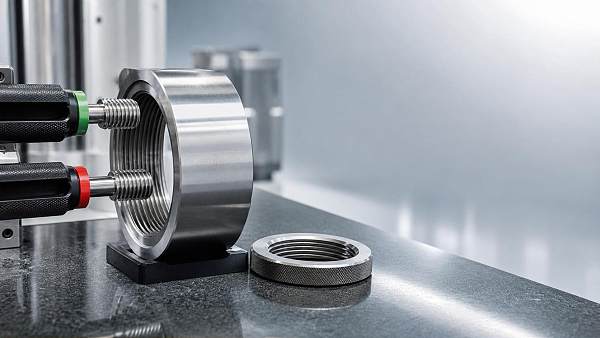
For an internal thread, a GO plug gauge is generally intended to verify that the functional diameter and related cumulative effects of pitch, flank angle, and lead do not make the thread too small for assembly. A NO-GO plug gauge is intended to check that the thread is not excessively large at the pitch-diameter condition. External threads are evaluated with corresponding ring gauges or other suitable methods. These descriptions are intentionally functional: a gauge does not independently measure every geometric feature of the thread.
The component drawing establishes a product tolerance zone. The gauge maker tolerance establishes how much the actual gauge may vary around its specified gauge size. Depending on the gauge system, wear allowance may also be included, particularly on GO gauges expected to experience routine use. Calibration uncertainty then affects the confidence with which the actual gauge dimension can be stated. These layers must be considered together rather than treated as unrelated numbers.
If a gauge is manufactured at one extreme of its permitted tolerance, it may still be conforming as a gauge. Yet its practical acceptance behavior can be meaningfully different from a newly made gauge located nearer the nominal target. That difference is most visible when inspected parts are close to their product limits.
Where manufacturing variation changes gauge behavior
Thread gauges are sensitive to several geometric characteristics. Pitch diameter is usually central to functional acceptance, but it is not the only contributor. A small change in lead, flank angle, taper where relevant, thread form, or truncation can alter the way the gauge engages the workpiece. Surface treatment and coating thickness can have the same effect if they are applied after the gauge’s critical geometry has been established.
Pitch diameter and functional size
For many standard thread forms, pitch diameter is the most influential dimension in determining assembly fit. A GO gauge that is effectively oversized for its intended condition can reject internal threads that are still within the product requirement. Conversely, a GO gauge that has become undersized through manufacture, damage, or wear may enter a thread that should have been rejected.
The same logic applies to external-thread ring gauges, though their adjustment, handling, and calibration approach differ. A ring gauge that is not set or verified correctly can create an apparent product trend that is actually a gauge condition problem.
Lead and accumulated pitch error
A thread may have an acceptable local pitch-diameter measurement yet develop a functional assembly issue because pitch errors accumulate along the engagement length. A long GO gauge engages multiple turns at once, so it can detect a combined effect that a short, localized measurement may not reveal. This is useful, but it also means gauge manufacturing quality must control lead accurately. A gauge with its own lead error may distort the functional result.
When a threaded feature is unusually long, high-precision, or safety-critical, relying only on a fixed limit gauge can be insufficient. Direct measurements of pitch diameter, lead, and form may be needed to understand why functional acceptance and assembly performance do not agree.
Flank angle and contact condition
Thread gauges contact the flanks, not merely the crests and roots. Flank-angle deviation changes the location and nature of contact. A gauge may feel tight because the workpiece flank angle is incorrect, because the gauge’s form is incorrect, or because burrs and contamination are interfering with engagement. Treating every tight gauge result as a pitch-diameter issue can send corrective action in the wrong direction.
This is especially important for coated, plated, heat-treated, or formed threads. Material buildup and distortion do not always affect the thread uniformly. A part can look clean at the crest while having an altered flank condition that changes gauge fit.
A practical investigation when results become inconsistent
When a threaded feature suddenly produces mixed pass/fail decisions, avoid beginning with a debate over operator technique. Start by preserving the evidence: identify the gauge, record its calibration status, segregate the questionable parts, and note the exact inspection condition. Was the thread inspected before or after coating? Was lubricant present? Was the component at a substantially different temperature from the gauge? Were the same engagement rules used by everyone?
Then separate the problem into three questions: is the gauge valid, is the workpiece condition repeatable, and is the gauge method appropriate for the requirement?
- Confirm gauge identity and intended use. Verify thread designation, class or tolerance position, handedness, standard system, gauge type, and whether the gauge is GO, NO-GO, setting, or inspection equipment. Similar-looking gauges are not interchangeable.
- Review the calibration record. Check the reported measured values, uncertainty statement, environmental conditions where available, calibration date, and acceptance decision. A “calibrated” label alone does not explain where the gauge sits within its permitted limits.
- Inspect the gauge physically. Look for worn flanks, dents, corrosion, embedded debris, damaged starts, handling marks, or evidence of unauthorized rework. Clean the gauge using a method compatible with its material and finish before repeating inspection.
- Repeat the functional check consistently. Use the specified engagement method. Do not force a GO gauge. Do not use excessive torque to make a marginal part pass. For a NO-GO gauge, follow the governing requirement for allowable engagement rather than applying an informal “feel” standard.
- Measure representative parts directly. Use a suitable metrology method to investigate pitch diameter and, when needed, lead and form. The goal is not to replace the functional gauge automatically, but to determine whether the observed condition belongs to the part or the gauge.
- Compare results against the correct acceptance scheme. Include product tolerance, gauge maker tolerance, wear allowance where applicable, calibration uncertainty, and any documented decision rule. Do not compare a direct dimensional result and a functional gauge result as if they answer exactly the same question.
This sequence is more reliable than immediately adjusting a ring gauge, replacing a plug gauge, or widening an internal inspection practice. Those actions may remove the symptom while leaving the original source of variation untouched.
Calibration confidence is not the same as product conformity
A calibration result tells you whether the gauge meets its assigned requirements within the stated measurement capability and decision rule. It does not prove that every previously accepted component is conforming, nor does it mean a borderline component has been evaluated without uncertainty.
Consider a gauge found close to one end of its allowable manufacturing range. It may still pass calibration. If that gauge is used to make a binary accept/reject decision on a product located close to its own boundary, the inspection system has little practical separation between gauge variation and product variation. This is where documented guard-banding or risk-based decision rules may be appropriate, provided they are consistent with the applicable specification and contractual requirements.
Guard-banding is not an arbitrary tightening of limits. It is a defined method for controlling the risk of false acceptance or false rejection when measurement uncertainty is significant relative to the available tolerance. The appropriate approach depends on the governing standard, the function of the threaded joint, the consequences of failure, and the measurement capability available. A highly loaded or pressure-retaining joint may justify a more conservative disposition process than a low-consequence fastening feature.
For this reason, calibration certificates should be reviewed as technical documents rather than stored only for traceability. Useful records identify the gauge’s measured condition, relevant nominal and permissible values, the reference system used, uncertainty, and the basis for conformity. If the certificate provides only a broad pass/fail statement, it may be difficult to assess risk when an inspection dispute occurs.
Coatings, wear, and the false comfort of a recent certificate
Thread gauge manufacturing tolerance is set during manufacture, but the gauge’s condition continues to change in service. GO gauges tend to see frequent contact and are therefore more exposed to wear. Repeated use can alter functional size gradually, while a single impact can damage a starting thread immediately. Gauges stored loose with other tools may acquire nicks that are not obvious until a part begins to hang up at entry.
Coated gauges require particular attention. A coating may improve wear resistance or corrosion resistance, but its thickness and uniformity must be part of the gauge design and verification approach. Applying a coating after final sizing without controlling the resulting functional dimensions can shift the gauge away from its intended limit. The same principle applies to refurbishment, polishing, or repair: a visually improved gauge is not necessarily a dimensionally valid gauge.
Recent calibration also does not eliminate the need for between-calibration controls. If the gauge is dropped, forced into a questionable part, exposed to corrosion, or used in a process generating abrasive contamination, its status should be reconsidered. A short functional verification using controlled masters or an interim evaluation procedure may be justified before returning it to routine use.
Making inspection decisions more repeatable
Repeatability improves when the organization clearly defines what the thread gauge is expected to prove. The work instruction should identify the correct gauge, preparation of the part, cleaning expectations, alignment, use of force, allowable engagement for NO-GO gauging, and the action required when the result is borderline. “Gauge until it feels right” is not a controlled method.
It also helps to distinguish product verification from process monitoring. Limit gauges are efficient for routine acceptance because they provide a fast functional decision. They are less effective at revealing whether a process is drifting toward a limit. Periodic variable measurement of pitch diameter or related thread parameters can show direction of change before the GO or NO-GO gauge begins producing failures.
For complex situations, keep the gauge result and the direct measurement result in the same investigation record, but do not force them into false agreement. A functional gauge may reject a part because of combined lead, flank, and diameter effects, while a single-variable measurement may appear acceptable. That difference is diagnostic information. It indicates that the next step should examine thread geometry, not simply repeat the same measurement.
When a gauge should be removed from service
Remove a thread gauge from routine use when calibration shows it outside its assigned limits, when visible damage affects engagement, when its identification is unclear, or when an abnormal inspection pattern cannot be resolved. It should also be held if a gauge result changes after a drop, repair attempt, unauthorized cleaning process, or suspected exposure to conditions that may alter its surface or dimensions.
The most defensible acceptance limit is created by a controlled chain: the correct product specification, a properly selected gauge system, manufacturing tolerances appropriate to that system, calibration with known uncertainty, disciplined handling, and a documented response to borderline results. When one link is treated casually, the gauge may still look like a simple pass/fail tool while quietly shifting the real boundary of acceptance.
Recommended News
 Sep 17, 2026How to select inline measurement systems for Middle East heatInline Measurement Systems Middle East: learn how to select reliable solutions for heat, dust, vibration, calibration, and production-ready data integration.
 Sep 16, 2026How to choose monitor stands that reduce neck strain at workMonitor stands can reduce neck strain by improving screen height, distance, and stability. Explore practical tips to choose the right ergonomic stand for a more comfortable workspace.
 Sep 15, 2026How to verify an importers directory for machinery before contacting suppliersImporters directory for machinery verification guide: assess legal status, technical fit, compliance, and service capability to build a reliable supplier shortlist.
 Sep 13, 2026How to assess calibration support from metrology suppliers in the Middle EastMetrology suppliers Middle East: learn how to assess ISO/IEC 17025 scope, calibration uncertainty, local support, turnaround time, and lifecycle cost.
 Sep 12, 2026How material fatigue causes cracks in safety-critical componentsMaterial fatigue can trigger hidden cracks in safety-critical components long before visible failure. Learn how cyclic loading, stress concentrations, inspection methods, and targeted controls reduce risk.
 Sep 10, 2026What to verify before choosing an optical micrometer supplier for wireChoose an optical micrometer supplier for wire with confidence. Verify real-line accuracy, calibration, integration, and support before you buy.
 Sep 08, 2026How to choose thickness gauges for pipes with limited accessThickness Gauges for pipes: learn how to select the right ultrasonic gauge and probe for tight access, curved surfaces, corrosion, coatings, and reliable readings.
 Sep 07, 2026How to choose anti-aging face serums for your skin typeantiagingfaceserums made simple: discover the best ingredients, textures, and routines for dry, oily, sensitive, or combination skin—plus tips for visible results.
 Sep 05, 2026How to choose sheet metal components for tight-tolerance assembliesSheet metal components for tight-tolerance assemblies: learn how to align materials, datums, forming, finishes, and inspection for reliable fit and repeatable performance.
 Sep 04, 2026What accuracy should a digital temperature humidity sensor have?Digital temperature humidity sensor accuracy explained: compare temperature and RH limits, resolution, drift, calibration, and installation effects to choose reliable performance for your application.
 Sep 03, 2026How to choose glamping tents for eco resorts in high-wind locationsGlamping Tents for eco resorts: discover how to choose wind-resistant structures, engineered anchors, and durable materials for safer, sustainable stays.
 Sep 02, 2026How to assess a bore gauge manufacturer in Latin America for measurement reliabilityBore gauge manufacturer Latin America: learn how to verify calibration traceability, repeatability, service support, and shop-floor reliability before you buy.
 Sep 01, 2026What accuracy factors matter most in advanced metrology calibration?Advanced metrology calibration: discover the key accuracy factors—from traceability and uncertainty to environment, probes, and software—for reliable decisions.
 Aug 31, 2026When does legal tech make sense for a growing business?Legal tech helps growing businesses streamline contracts, compliance, IP, and audit controls. Discover the key signals, practical tools, and steps to scale with confidence.
 Aug 30, 2026How manufacturing tolerance affects thread gauge acceptance limitsThread gauge manufacturing tolerance affects acceptance limits, calibration confidence, wear risk, and inspection consistency. Learn how to prevent costly thread gauge errors.
 Aug 29, 2026How to choose office supplies that reduce waste in shared workspacesOffice supplies can cut waste and costs in shared workspaces. Discover practical procurement tips for durable, refillable, low-packaging products.
 Aug 28, 2026How to compare metrology equipment vendors for calibration supportMetrology equipment vendors: compare calibration scope, ISO/IEC 17025 support, downtime, documentation, and lifecycle costs to choose reliable service.
 Aug 27, 2026What to evaluate before choosing industrial inspection systems in AsiaIndustrial Inspection Systems Asia: evaluate accuracy, cycle time, automation, traceability, and local service to choose a reliable solution for smarter quality control.
 Aug 26, 2026Do dermarollers actually improve absorption of skincare productsDermarollers can improve skincare absorption, but not always safely. Learn when they help, which products to pair, and how to avoid irritation for better skin results.
 Aug 25, 2026What makes a high accuracy CMM probe reliable at tight tolerancesHigh accuracy CMM probe reliability depends on repeatability, stylus stability, calibration integrity, and system fit. Learn what ensures trusted results at tight tolerances.
 Aug 24, 2026When does an automated trade platform make sense for growing teams?Automated trade platform adoption makes sense when growing teams face supplier complexity, compliance risk, and limited visibility. Learn the signs, ROI factors, and how to scale with control.
 Aug 22, 2026How to vet an industrial measurement equipment supplier for calibration traceabilityIndustrial measurement equipment supplier selection starts with calibration traceability. Learn how to verify ISO/IEC 17025 evidence, uncertainty, and audit-ready documentation.
 Aug 20, 2026What is driving demand in the optical metrology market right nowOptical metrology market demand is rising as manufacturers need faster, non-contact, high-precision inspection for semiconductors, EVs, electronics, and automated production lines.
 Aug 18, 2026How to integrate a digital gauge RS232 output with SPC softwareDigital gauge RS232 output integration with SPC software: learn how to ensure stable data capture, traceability, and scalable deployment while avoiding hidden quality risks.