How Modular Building Wind Load Resistance Is Calculated
Time
Click Count
Understanding how modular building wind load resistance is calculated matters well before fabrication begins. For off-site construction, the wind design check is not a paperwork exercise. It affects module geometry, connection detailing, transport strategy, installation sequencing, and the evidence base used for compliance review.
In practical terms, modular building wind load resistance is the ability of a factory-built structure to withstand lateral and uplift forces without loss of strength, serviceability, or enclosure performance. The calculation process combines code-based wind actions, structural analysis, and measured data from materials, joints, and system tests.
That combination is attracting wider attention across industrial and commercial projects. Faster delivery is valuable, but technical confidence depends on verifiable numbers. In that environment, the G-IMS approach to benchmarking, standards alignment, and measurement-driven evaluation provides a useful lens for comparing claims with actual engineering evidence.
What the calculation is really trying to prove
Wind does not act on modular buildings in a single, uniform way. Pressure changes with height, terrain, roof shape, building importance, local topography, and openings in the envelope. The purpose of calculation is to convert those variables into design loads that the module and its connections can safely resist.
For modular systems, this check usually has two levels. One level addresses the completed building in service. The other addresses temporary conditions, including lifting, transport, craning, and partially assembled structures. A module may pass the final condition and still be vulnerable during installation if temporary wind cases are ignored.
That is why modular building wind load resistance is not limited to wall studs or corner posts. It includes diaphragms, tie-downs, inter-module connections, base frames, roof assemblies, cladding fixings, and anchorage into the permanent foundation.
The main variables used in wind load calculations
Most design methods start with a reference wind speed from the applicable code. Depending on jurisdiction, the designer may use ASCE 7, the International Building Code, Eurocode EN 1991-1-4, the National Building Code of Canada, or local standards derived from similar principles.
The calculation then adjusts that base value using several modifiers. Although the notation changes by standard, the engineering logic stays fairly consistent.
- Basic wind speed or reference velocity for the project location
- Exposure category, reflecting surrounding terrain roughness
- Topographic effects from hills, escarpments, or ridges
- Importance or risk category tied to occupancy and consequence
- Internal pressure coefficient linked to enclosure classification
- External pressure coefficients based on roof and wall zones
- Gust or dynamic response factors for flexible structures
- Load combinations required by the governing code
A simplified pressure expression often takes the form of velocity pressure multiplied by exposure terms and pressure coefficients. The result is then applied to defined surfaces and structural elements. From there, engineers check bending, shear, axial force, overturning, uplift, deflection, drift, and connection demand.
Why modular buildings need more than a standard wall check
A site-built wall can often be assessed as part of a continuous structural frame assembled in place. Modular buildings behave differently because each unit is manufactured as a transportable volume. That means wind forces must move through a series of discrete interfaces.
Those interfaces create design questions that are easy to underestimate. Where exactly is the lateral load path? Which bolts or welds transfer uplift between modules? How much slip can a stacked connection tolerate before serviceability becomes an issue? The quality of answers depends on traceable data, not assumptions.
How engineers calculate modular building wind load resistance
The workflow usually begins with the building’s geometry, site conditions, and code basis. Engineers define the module layout, total height, roof type, façade features, and intended occupancy. They also identify whether the building is enclosed, partially enclosed, or open, because that classification changes internal pressure significantly.
Next comes the determination of wind pressures for walls, roofs, corners, edges, and local zones. Corner areas often experience the highest suction. For modular systems, those localized effects can govern cladding attachments or roof-edge details even when the main frame remains well within capacity.
The structural model then distributes those pressures through the module. Depending on the system, resistance may come from steel moment frames, cold-formed wall panels, cross-braced bays, stressed-skin action, or hybrid timber-steel assemblies. The analysis checks both individual modules and the assembled building.
After member forces are known, connection design becomes central. In many modular projects, the controlling limit state is not the primary member. It is the connector, anchor, screw pattern, plate thickness, weld detail, or bearing condition at a repeated joint.
Finally, the design is validated against serviceability and strength criteria. Excessive drift can damage partitions, glazing, façade joints, or MEP interfaces. So modular building wind load resistance must be judged by both ultimate capacity and operational stability.
Where measured data strengthens the calculation
Code formulas define the load side, but reliable performance also depends on the resistance side. That is where measurement quality matters. Material properties, fastener behavior, weld consistency, dimensional tolerances, and panel stiffness should be supported by testing or validated manufacturing controls.
This is especially relevant in a benchmarking environment shaped by G-IMS. A technical review should not stop at design spreadsheets. It should examine whether the underlying inputs come from accredited laboratories, repeatable inspection systems, and standards-based metrology.
For example, non-contact vision inspection can verify connector placement and assembly precision. Advanced metrology can confirm frame geometry and tolerance stack-up. Environmental monitoring can help evaluate seal durability and enclosure behavior under variable humidity or temperature. Each data stream reduces uncertainty around modular building wind load resistance.
Common test references and evidence sources
The exact evidence package depends on code and product type, but several references appear frequently in project reviews.
- Structural calculations stamped under the local regulatory framework
- Material mill certificates and mechanical property data
- Connection tests for bolts, welds, screws, or anchors
- Envelope tests for air, water, and structural pressure resistance
- Factory quality records aligned with ISO or equivalent controls
- Calibration records traceable to recognized standards bodies
When those inputs are fragmented or inconsistent, the calculation may still look complete on paper. The real problem is comparability. Without measurement discipline, two suppliers may claim the same modular building wind load resistance while relying on very different assumptions and verification depth.
Frequent blind spots in procurement and technical review
One common mistake is comparing only the stated design wind speed. Wind speed alone does not define performance. Exposure category, pressure coefficients, enclosure assumptions, and safety factors can change the actual demand substantially.
Another issue is treating system tests and analytical checks as interchangeable. They serve different purposes. A pressure chamber test may validate a wall assembly or façade detail. It does not automatically prove the global lateral capacity of a stacked modular structure.
Transport and erection conditions are also missed too often. During craning or temporary bracing stages, the structural system may be less redundant than in the final configuration. Those stages need their own wind criteria, especially for taller modular projects.
A final blind spot is documentation quality. When calculations use proprietary assumptions, but the supporting test scope is unclear, the review becomes difficult to reproduce. A stronger package links every key claim to a standard, a test report, a calibrated instrument, or a clearly defined design method.
How to use the results in real project decisions
In business terms, modular building wind load resistance should be read as a structured decision input. It informs supplier qualification, risk allocation, insurance discussions, installation planning, and lifecycle maintenance expectations.
A useful review framework includes four questions. Is the governing code identified clearly? Are temporary and permanent wind cases both covered? Do calculations map to actual connection details and manufacturing tolerances? Is the resistance claim backed by measurable, traceable evidence?
That approach fits broader industrial evaluation practice. G-IMS emphasizes the movement from raw measurement to actionable insight. Applied here, that means translating structural numbers into a benchmarkable technical position, rather than accepting isolated headline values.
The next step is usually not a larger report. It is a cleaner comparison set. Define the wind hazard basis, request the load path assumptions, verify the connection testing scope, and check whether the evidence is traceable to recognized standards. That is where a credible modular building wind load resistance claim becomes easier to trust, compare, and approve.
Recommended News
 Sep 30, 2026How to verify IEC compliance when selecting electrical test systemsElectrical test systems IEC standards: learn how to verify compliance through method scope, calibration evidence, safety documentation, and witnessed testing.
 Sep 29, 2026How water utilities can prepare sustainability reports for assuranceSustainability reporting for water utilities: learn to build assurance-ready metrics, controls, evidence, and governance that strengthen trust, compliance, and resilience.
 Sep 20, 2026How to choose sanitary ware that meets drinking water safety standardsSanitary ware for drinking water: learn how to verify certifications, wetted materials, hygiene design, and traceability for safer, compliant installations.
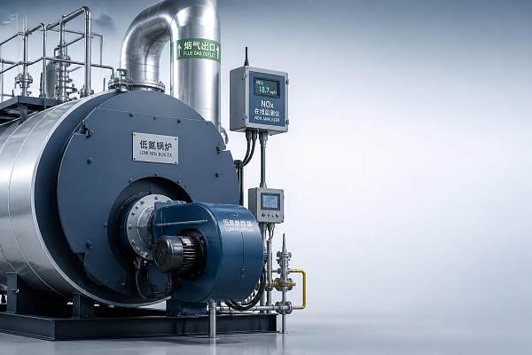
 Aug 21, 2026When do industrial boilers need low-NOx burners to meet emissions limitsIndustrial boilers may need low-NOx burners when stricter permits, fuel changes, or upgrades reduce compliance margin. Learn the key triggers before emissions risks cause downtime.
 Aug 14, 2026How advanced metrology standards affect measurement traceability and audit readinessadvanced metrology standards strengthen measurement traceability, improve audit readiness, and help QA teams defend every result with confidence.
 Aug 08, 2026How to Evaluate a Global Trade Platform for Supplier Reach and Compliance RiskGlobal trade platform evaluation starts with usable supplier reach and compliance clarity. Learn how to spot weak records, hidden logistics risks, and decision-ready supplier data.
 Jul 20, 2026High Voltage Cables: Key Selection Factors for Reliable Power ProjectsHighvoltagecables selection made practical: learn how to compare insulation, installation environment, compliance, and lifecycle cost for safer, more reliable power projects.
 Jul 15, 2026Environmental Sensor Systems for Continuous Compliance MonitoringEnvironmental Sensor Systems for continuous compliance monitoring across production, labs, and utilities—improve audit readiness, data reliability, and operational control.
 Jul 14, 2026Eco-Friendly Furniture: What Actually Affects Cost, Durability, and ComplianceEco-friendly furniture explained: compare real cost drivers, durability, certifications, and compliance proof to avoid greenwashing and choose smarter long-term value.
 Jul 12, 2026What CE Certification Means for Photonic Sensor System CompliancePhotonic sensor systems CE certified: learn what CE really covers, which compliance risks matter most, and how to verify claims before choosing industrial sensing equipment.
 Jul 10, 2026How to Evaluate a Cuplock Scaffolding Manufacturer for Safety and Lead TimeCuplock scaffolding manufacturer selection affects safety, quality, and delivery. Learn how to verify process control, load data, traceability, and realistic lead times.
 Jul 09, 2026Data Intelligence Protocols for Smart Factories: Key Standards to KnowData Intelligence Protocols for smart factories explained: discover OPC UA, MQTT, ISA-95, ISO/IEC 17025, and IEC 62443 to improve traceability, security, and quality decisions.
 Jul 06, 2026How Modular Building Wind Load Resistance Is CalculatedModular building wind load resistance explained clearly: learn how engineers calculate loads, verify connections, and use test-backed data to reduce risk and improve project confidence.
 Jul 05, 2026What CE Certified Measuring Equipment Really Covers Before You BuyCE certified measuring equipment may meet EU compliance rules, but what does it really cover? Learn how to verify safety, EMC, documents, and performance before you buy.
 Jul 04, 2026Life Sciences Measurement Trends in 2026: Where Quality Control Is TighteningLife sciences measurement trends for 2026 show why quality control is tightening fast. Explore key risks, data integrity demands, and practical steps to stay compliant and competitive.
 Jul 01, 2026Calibration and Measurement Standards USA: What Matters MostCalibration and measurement standards USA guide traceability, uncertainty, and audit-ready measurement control. Learn what protects quality, compliance, and confident decisions.
 Jul 01, 2026ISO 10360 Europe: Key Compliance Changes for 2026ISO 10360 Europe 2026 compliance changes will reshape CMM validation, traceability, software control, and audit readiness. See key risks, impacts, and practical steps to prepare.
 Jun 29, 2026Supplier Evaluation Checklist for Industrial Technology Sourcing in 2026Industrial Technology Sourcing supplier evaluation in 2026 demands more than price checks. Explore a practical checklist to reduce risk, verify compliance, and choose resilient suppliers with confidence.
 Jun 27, 2026First Aid Kits Wholesale: Cost, MOQ, and Compliance ChecklistFirst aid kits wholesale guide covering landed cost, MOQ, customization, and compliance. Compare suppliers smarter, reduce sourcing risk, and buy market-ready kits with confidence.
 Jun 26, 2026How to Evaluate a First Aid Kits Distributor for Compliance and Supply StabilityFirst aid kits distributor evaluation guide: learn how to verify compliance, traceability, refill control, and supply stability before choosing a safer, audit-ready partner.
 Jun 25, 2026Steel Rebar for Construction: Grades, Sizes, and Load PerformanceSteel rebar for construction explained: compare grades, sizes, tolerances, and load performance to choose safer, code-compliant reinforcement with greater long-term reliability.
 Jun 24, 2026How Import Data Reveals Supplier Risk and Price Shifts in 2026Import data reveals supplier risk, price shifts, and sourcing concentration in 2026. Discover early warning signals that help teams protect costs, continuity, and smarter supply decisions.
 Jun 23, 2026How to Evaluate an Outdoor Lithium Power Station Factory in 2026Outdoor lithium power station factory evaluation in 2026 starts with quality control, compliance, and test evidence. Discover how to compare suppliers and reduce sourcing risk.
 Jun 22, 2026Organic Chemicals: Key Purity Risks and Compliance ChecksOrganic chemicals can pass on paper yet fail in practice. Learn the key purity risks, compliance checks, and supplier review points needed to protect quality, safety, and process stability.